The Diary of the Building of a 5" gauge Stirling Single |
|
|
|
|
|
|
|
Connecting rod - motion plate |
|
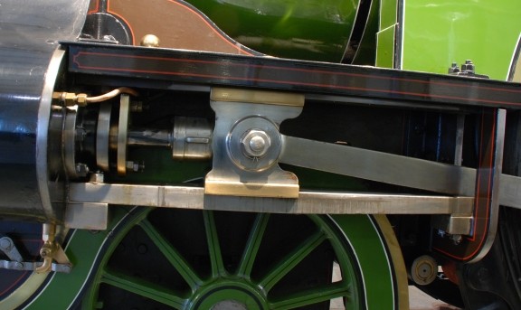
| This picture I took at the
National Railway Museum of the exhibited Stirling Single.
|
|
| 24th October 2013. The start of the fabrication of the motion plate. Sadly I bought material which was too thick so I have had to mill it down to thickness and then will have to file to make a good surface. | 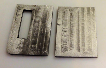 |
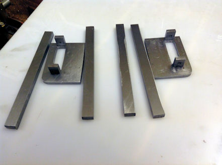
| 25th October 2013.The
second motion plate was milled and filed to the right size.
The opening is slightly larger as I am to use slightly thicker slide bars material. The support pieces were turned on the lathe in a 4 jaw chuck with the material centred in the chuck. This was turned down to provide a riveting head of 3mm The four pieces were then riveted into place. The slide bars were prepared earlier. |
 |
| This is a photo taken at the NRM and it shows that the slide bars end flush with the rear side of the motion plate. That I will be able to achieve with the loco I am building. | 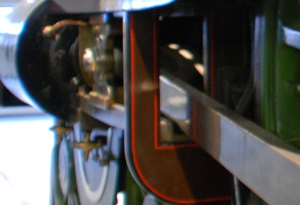 |
| 18th November 2013.
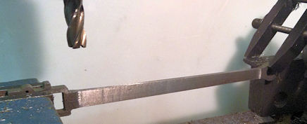
Work started on the water jet cut Connecting rods. The machining was all carried out on the milling machine to bring the part to size at the Cross head and between the wheel end and the cross head end which was thinned down to size. A file will be used to bring the parts to a good finish as they are not painted on the original. |
 |
| 24th November 2013.
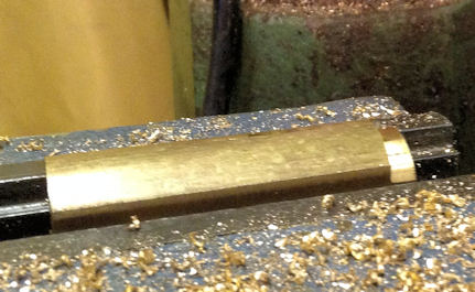
The big end bearing had to be made from round stock which first had to be milled rectangular. the photo show that the two side have been machined and the cutter is now to cut the third side. |
 |
| Here the blank is fully machine ready to be cut in to the 4 pieces making up the two big end bearing. | 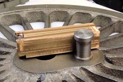 |
| Two of the piece that need to be soldered together for final finishing. | 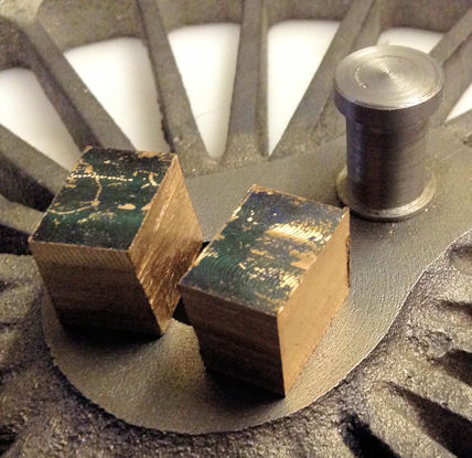 |
| 25th November 2013.
The parts of the Big end bearing had to be soft solder together to that the final machining could take place. Flux was applied to the join line and then the whole was clamped so that it did not move but not so tight that the solder could not penetrate the joint. |
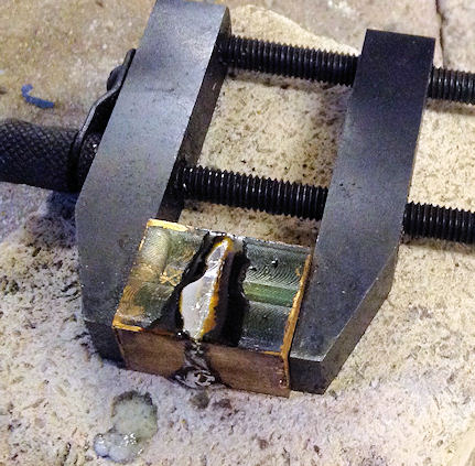 |
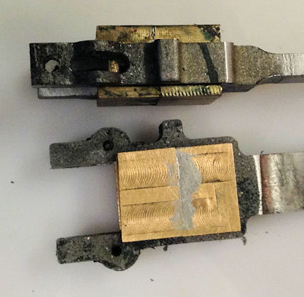
| The big end bearing is held in the vice ready to cut the top bottom and two side grooves | 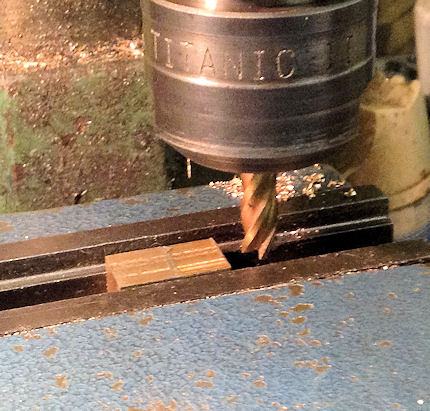 |
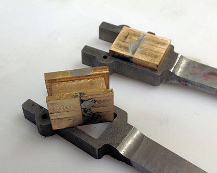
| Machining completed and one
big end bearing has been inserted in a connection rod whilst the
other sits on the top so that you can see the machining.
In now remains to drill the holes in the centre of each bearing and then part the two halves. |
 |
| 26th November 2013.
Today I decided to mill out the holes for the keeping wedge. As I did not have a 2mm slot drill I decided to use my 3mm in its place. At that moment I could see no reason why only a 3.32" hole was required. After the slots had been cut top and bottom I had to drill the hole for the keeper back piece and then ream out. The photo shows the reaming operation completed. Note the piece of paper used to make sure the part did not slip in the vice and it proved to be as expected. It did not slip. |
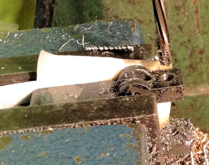 |
| Two photos to show the parts
as finished today.
The bearings themselves still have to be bored to size and then the two halves separated but not before the pairs have been marks so that they cannot be mixed up. |
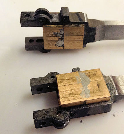
|
| 28th November 2013.
The big ends are nearing completion with the making up of the fixed and moving fixtures for the bearing blocks. Still to do is the tapped hole for the retainer and boring out the big end bearings themselves. |
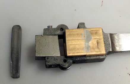 |
| 11th December 2013.
Since carrying out the last section I have purchased an Optical centre punch and very fine it is too. The bearing were each marked out so that the new centre punch could put in a marking centre which was enhance with a larger centre. This was then centred in the four jaw chuck and drilled out with a hole smaller than the required size. |
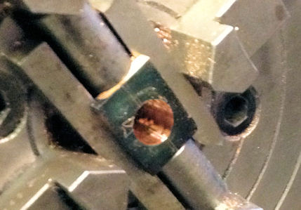 |
| The holes was then opened out to accommodate a test size piece of bar which at the end was a fraction smaller than required so that I knew when I was reaching the size and then one dead to the size I wanted. | 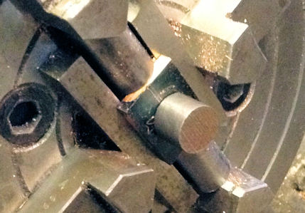 |
| Both the bearing are now temporarily installed in the connecting rods. | 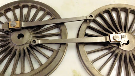 |
| 13th
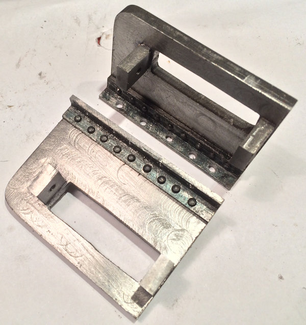
November 2015 So after two year break work now continues on the Motion Plate and thus this section on the web site. Four hours in the workshop has resulted in machining to size the 5/16/" angle pieces and the drilling of 18 1/16" holes to take the 18 1/16" rivets, putting the rivets in the holes individually and cutting to length and finally using rivet snaps I made to finish off the riveting home. The holes were drilled to clear 6BA bolts which will be used to secure the motion plates to the frames when the holes have been drilled but that cannot take place until the cylinders are fitted. |
 |
| 17th
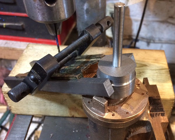
November 2015 I asked an engineering friend a question regarding the guide bar and this was his reply. So this is the plan of action ...... Regarding the guide bars. There is of course always more than one way to do a job but herewith offer the following. Drill the fixing holes for the rear cover tapping size for the studs or bolts. The photo shows the holes drilled You can machine the seating on the rear cover on which the guide bars are bolted making sure that they are equidistant from the hole in the cover that the piston rod goes through. Careful measurement here or a little 'button'' machined with a spigot to fit the hole in the cover for the gland and the outer diameter to the dimension of the inside of the guide bars. I have already machined the seating on the rear cylinder cover but the guide bar being made thicker will need milling down so the use of the button idea will be implemented. I made up the separation of the guide bars using the cross heads in a pair of guide bars. Then the button was machined to fit between the guide bars. |
 |
| I needed to file the
Motion Bracket to allow the guide bars to pass through. Clamp the slide bars to the cross head with a cigarette (or whatever) paper in between each bar and the seating on the cover, to allow for running clearance. Put the motion bracket on the other end of the bars where is it going to be, then fix the slide bars to the rear cover. I have not used the paper idea for this trial fitting but it is all looking fine but final fitting to be carried out . The picture show that I now have the bars and the motion bracket all mounted together BUT I have used the wrong motion bracket. Final checking for the correct alignment is still to be done when the cylinder is bolted into position. Put the assembly now into the cylinder which has already been bored and machined on all faces and lay it on the surface plate with the side which goes to the frames on the surface plate. I have used the loco frames as they have steps along the frames which have to be taken into account so by using the frames errors are eliminated. |
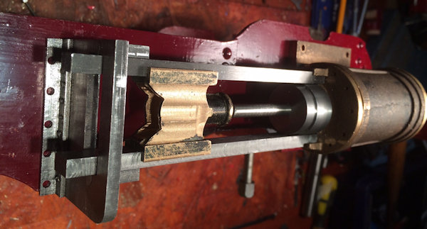 |
| This is still to do
!!!! The guide bars are now horizontal and parallel to the surface plate lengthwise between the cover and the motion bracket. Run the clock over them from cylinder cover to motion bracket to check. If they are not make adjustments to the motion bracket as the the cylinder is the fixed point. They will also be in line with the cylinder side that is going to be bolted to the frames. Run a clock over the slide bars at right angles to them to get them parallel to the surface plate (the cross head will be horizontal to the surface plate) by rotating them with the rear cylinder cover until the same clock reading is obtained on each. It will pay off in the end if they are right. To hold the bars in this position nip up the extended piston rod onto a bar or plate across the bore at the front of the cylinder. The slide bars etc., can now be dismantled from the cylinder cover and the holes for the fastenings for the rear cylinder cover drilled and tapped using the cover as the jig. If you want to be fussy and also have the room to do it, then dowels can also be fitted. Drill the cover holes out clearance for the fixings. |
So
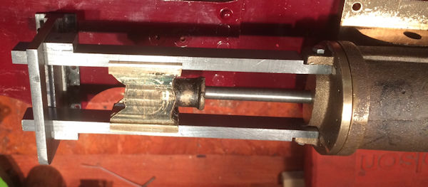
this is what I did I was aware that critical alignment was necessary and spent the last few days working through several methods I might achieve success. I decided to start with fixing the Guide bars to the end cap of the Cylinder. To do this the end cap was drilled with tapping size holes for 5BA which then acted as a guide to spot through onto the guide bars. So with the end cap opens out to the clearance size for the bolts and the guide bars tapped to take the bolts and the necessary bolts shortened the whole lot was assembled onto the cylinder. Checks were made ensure the correct positioning of all parts and the bolts were tightened up to hold the guide bars in place. To correctly drill the cross head a centre drill was put in the lathe and with the cross head between the guide bars and pressed against the end cap the centre drill was used to give a precise centre start to the hole in the cross head. The cross head was then set up in a vice under the pillar drill and the completion of the drill of the hole achieved. I now need to shorten the piston rod finally attach to the cross head and complete the fixing to the loco of the motion bracket. |
| The result |
 |

