The Diary of the Building of a 5" gauge Stirling Single |
|
|
|
|
|
|
|
Completion
of the build Part 13
|
|
|
6th
September 2019 102
days since the return of the loco for me to complete
So
let's look at the original list to see what has and has
not been done.
1. the regulator does not operate All sorted 2. Sight glass fitting need aligning and glass fitted All sorted 3. Make the boiler door catch and fit Not yet sorted 4. Sort out the coupling to tender Completed 5. Fix chimney to smoke box Completed 6. Amend the fixing of the cover plate above oiler Completed 7. Sort out axle pump as will not fit under the boiler Completed 8. Provide the
blower outlet in the smoke box
Not yet sorted
9. Seal up the
bottom of the smoke box so that a vacuum can form to draw the
fire
Not yet sorted
10. Fit lugs
on the side of the boiler where it will sit on the frames
adjacent to the firebox
Not required boiler sits level
11. Painting
Yes progressing well
12. Make up
the Cab spectacles All sorted and
glass fitted
and
still to do !!!
Complete
all the pipework :-
1. to
whistle
2. to dummy
whistle
3. to axle
pump -- Started !!
4. to
injectors
AND
do more lining
out !!!!
|
|
|
In
the afternoon I was helping the set up for the 90th Birthday
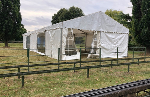
party of MMES. The photo shows the large tent where tomorrow
model will be displayed.
|
 |
| 7th
September 2019 103 days since
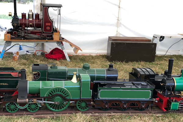
the return of the loco for me to complete The 90th Birthday party of the MMES where I am a member and also the club hosted the Southern Federation rally. My Stirling Single was on display amongst may other locomotives built by members of the club, a proud moment for me as it certainly did not look out of place.. |
 |
| For
the birthday party there was a wonderful cake made depicting the
club's logo so with such a busy day no actual work was done on
the loco. |
 |
|
8th
September 2019 104
days since the return of the loco for me to complete
Having found during the process of putting the loco back together that the reverser was in an inoperable location it was moved back towards the rear of the cab and the operating lever extended by about 25mm |
 |
|
As
the trailing wheels overlap the location of the fixing bolt it
was changed for a countersunk screw and all now fits together
so far but not until the sides are put on again will I know
for sure !
|
 |
| 9th
September 2019 105
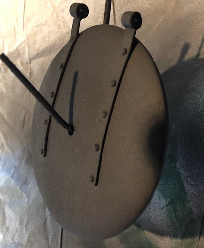
days since the return of the loco for me to complete The Smokebox door was sand blasted and then sprayed with the Ultra High Temperature black paint similar to that used for the chimney. |
 |
| The
reversing arm which was extended is now primed ready to paint
green as it can be seen behind the main driving wheels. |
 |
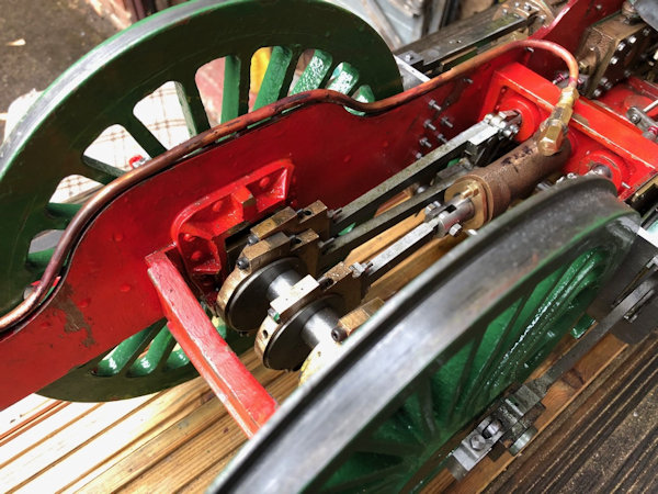
| Pipework
from the top of the Axle Pump which will link to the bypass
valve, which is not yet fitted so cannot be completed. There are no known drawings showing the routes of the pipes so it is all trial and may be error ... |
 |
| 10th
September 2019 106
days work on the loco since it was returned to me. The reversing lever shaft was painted, |
 |
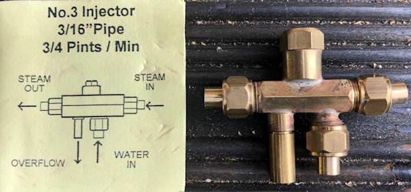
| Whilst
waiting for the paint to dry I looked through my parts which are
yet to be fitted and though I had better make a note of how the
injectors are connected. A good diagram came with the Part from
the supplier. |
 |
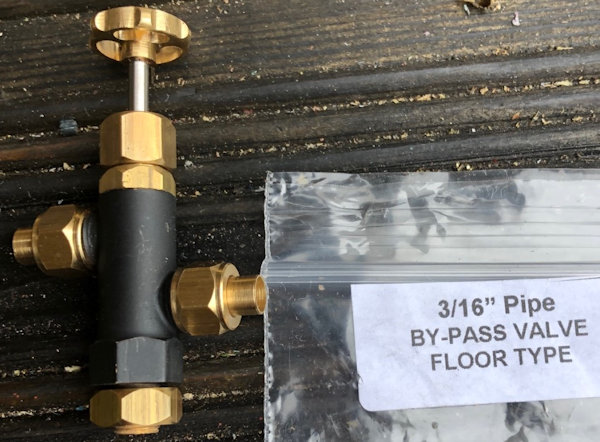
| This
is the bypass valve but I have to workout how to fit this to the
axle pump. |
 |
| The
actuator for the reversing lever has an arm which passed very
close to three bolt heads. one bolt hole I was able to counter
sink but the other two no chance but the counter sunk screws
give much better clearance then the bolt heads. |
 |
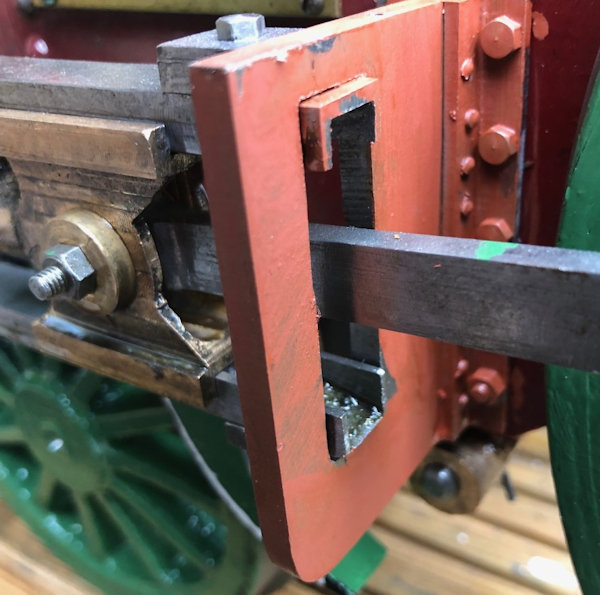
| The motion brackets
have now a coat of Red Oxide primer. The green paint on the
connector will be removed !!! |
 |
| 11th September 2019 Spent time working on the design of a new blast Exhaust Manifold as described by a friend from MMES, their design is in the picture. |
 |
| 12th September 2019 The new Exhaust manifold arrived and I decided to machine it. First the two ends were machine and threaded the second end was held in a purpose made threaded holder and the second end machined and threaded. Then the third part of the T was marked out to find as best one can the centre of the part and a centre pop hammer in. Then using a laser pointer the part was adjusted in the 4 jaw chuck to bring it central. It was then centre drilled so that a revolving steady could be used and then the out side was machined to size It was then drilled through to meet the transverse hole.. |
 |
| Then
a saw cut was made to provide a space to insert a centre babble
which covered the transverse hole and extends up about 3mm into
the exhaust port. The whole ides of making this came from an article in the MMES magazine where the author made a set of swept exhaust pipes link, but there was not enough space to do that in the Stirling Single. The photo shows the divider silver soldered into place with good penetration of the solder as evidenced by the marks inside. |
 |
| The replacement part
is not installed and a need exhaust port is to be made which
will fit the threaded external part. The half size of the 3/8" hole must not be less then the full size of the 7/32" hole in the top of Blast Nozzle and by my clculations all is good !! |
 |
Link to next page |
|
