 |
29th April
continued
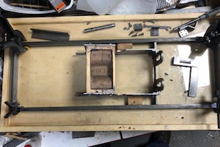
The four
corners were linked part drilled and bolted part glued.. While the super
glue set the corners were held in place by light weight clamps.
Checks were made that the corners were at right angles.
Sorry about the reflection but the surface plate is a piece of
glass.
When setting the cylinders in place the front pair of angle face
forwards !!!
|
|
30th April
2023
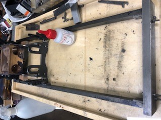
The last
angles are stuck in place to secure eventually the cylinder block
to frames.
|
|
So the
holes of the previous glued angle parts is done and the photo
shows the final glueing up using the wooden block to centre at the
rear. before the last gluing of the frames followed by drilling. I
guess they will be unbolted many times before the loco is in a
finished state.
|

|
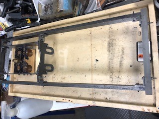
1st May 2023
All the angle pieces now drill ed and fitted temporarily as they
will need to come off again and set the right way up..
|
|
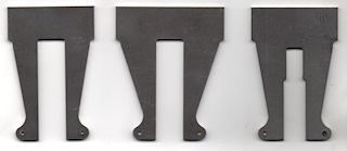
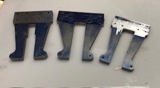
So
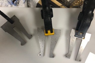
the next parts to consider are the horn plates for the loco. I had
these laser cut months ago. They are three different profiles from
left to right, Front Centre, Rear. the plans show the positions
based up on the centre line of the horn blocks. They will be
covered in marking out blue and the the fixing points marked and
drill as a pair in each case. The location of each will be marked
and drilling on the side pieces of the chassis which will also be
bolted together so that they are a marched pair.
So a lot to think about and prepare.
|
 |
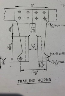
This is
from the plan and shows that rivets are required !!!! I must check
I have plenty in stock !!
|
|
2nd May
2023
The horns
were glued together in preparation for being drilled.
|
|
Marking out
fluid applied so marking out can be done soon.
|

|
3rd May 2023
Measuring the
position for the horns was not easy as I had to add inches and
fraction of inches and then subtract half the width of the horns.
Eventually is was achieved. The measurements were double checked
and then treble checked as I did not want to make a mistake.
|

|
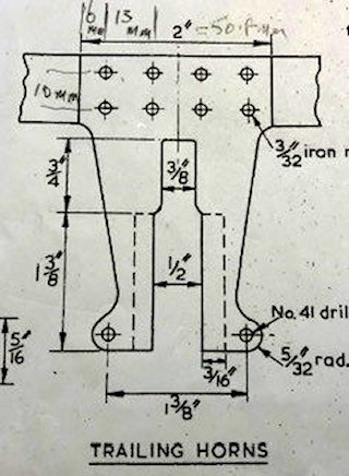
I need to
establish dimension which are not initially readily seen on the
plans. The plan indicates that the part which slides in the horn
and its added block is 1/2" wide which with the horn itself 1/8"
indicates that the block must have a thickness of 3/8"
|

|
The spacing
of the rivets is 13mm horizontally and 10mm vertically distance
from end is approx 6mmm!!
Metal and rivets not ordered from Maidstone Model Engineering.
|
|
5th May
2023
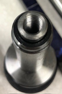
Made up the needed adaptor from M12 to 3/8"UNC for the new
mill cutter so the the shaft that holds it in place can join with
it. A second one was made for the drill holder
|
|
8th May 2023
After a
break to watch King Charles III Coronation and Coronation Concert
I decided to finish drilling all the rivet holes in the axle
box horns.
|
|
|
|
|
|
|
|


