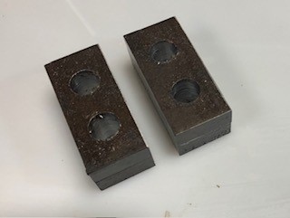
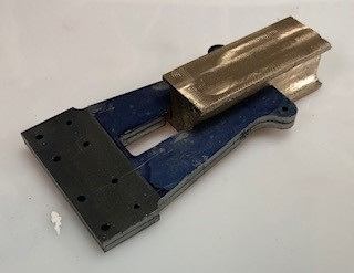
The next items to machine are the axle boxes. The main ( at the top of the picture) and trailing (at the bottom of the picture) axles boxed have different dimension hence the two different piece of bronze bar.
First I will need to bring the bars to datum ready so that they are square faces to each side prior to making out.
Then I will be able to machine the recesses each side.
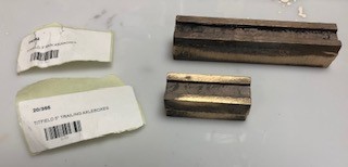
Preparing to machine the coupled Axles Boxes. The plan for the 5" Axle boxes is separate from that of the 3 1/2" so the correct disgram was extracted from the plans and printed out .

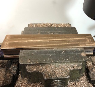
The machined of the recess in the axles boes was set up carefully in the mill vice so the it was truly parallel with the bad travel.

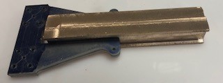
Whilst they look similar they have different dimensions!! Still the trailing axles boxes are fully machine save for cutting and drilling.

The cranks blanks are super glued together and ready for drilling in the machine vice.
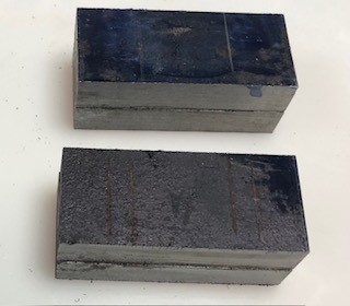
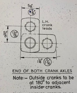
Both sets of cranks were centre drill, then 1/4" then progressively until they were reamed 7/16", they now need to have the ends brought to size.
This did not go well as the holes one side are not in the centre which indicates that the vice is poor quality and does not hold the pieces accurately !! I have another, more precision, vice and I will try again !!!

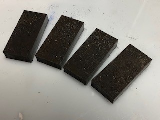
So after the disaster of yesterday 4 new pieces of steel were cut from a stock piece and will be machined in due course. I stead of them being machined separately I will glue that together and thus machine as one piece using a different machine vice.
They have still to be filed along all edges so that they can be glued together for machining and drilling.
I have bought an edge finder so today it was learning how to use it with my DRO.
Finding the centre line of a work piece with DRO
1. find the edge of piece on x axis and zero with the Xo button
2 find the edge on the x axis the other size and zero with the X button
3. press the ½ button and this will give the location of the centre of the piece on the X axis.
You can do the same but substituting the Y axis controls e.g. Yo and Y
And a simple test fopund that this works !!

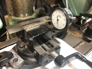
After the failure to drill perpendicular to the side of the cranks a new set up follows on from the alignment above.
The pair of crank pieces were glued together and allowed to set. Then the sides were milled to ensure to sides and identical width.
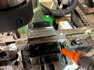
then the X axis was locked. First centre drill and then the holes drill by progressively larger drill until finally the hole was reamed to size.
Then the X axis was released and moved to the position of the other holes. and again the drilling procedure follows as above.
This time with the better Vice the holes were aligned with the sides.

