31st May 2023
The next item to be machined is the crack axle separate part and then assemble.
Whilst most loco have Right Hand crank leading my research shows that the GWR used in general left hand lead, which is shown on the plans and that is what I will use..
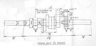
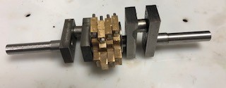
The photo shows the cranks with their end pieces set in-place. They are now left to set overnight at least.
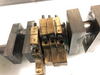
I have found that I have not yet drilled nor tapped the eccentrics for their setting Allen Bolts !!!
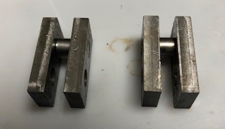
The other parts of the crank angle were machine and after one failure the parts mated up well. In the picture you can see the crank axle the centre and right hand piece are not yet fixed but the left hand has its adhesive applied and is now setting. the the alignment as good as to be expected!!!
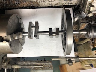
The first thing I did to day was to drop the centre part of the crank axle on the floor. After 2 hours and not found I decided to make another. When mde one end was Loctited onto the crank leaving one end open to fit the eccentric centres on in due course.
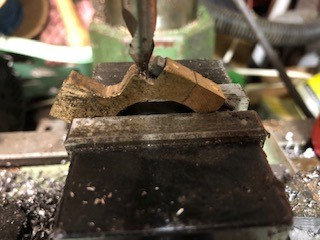
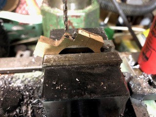
The remaining two centres of the eccentrics were drilled and reamed so all that now need to be done is to drill and thread for a locking Allen screw.
Eccentrics drilled and tapped for M4 allen screws
Sorry for the delay in posting items of engineering but I have been diagnosed with needing a hip replaced so that took priority for appointments etc.
Still back at the mill / drill now
The photo shows the setting up with the second stage of the edge finder which then when press the 1/2 button showed me how far to move the Y axes to reach the centre.

7442 Gear grab Saxby
7443 Back gear Saxby
20259 Side Stirrup
20260 Long lift link Saxby
20439 Ash Pan bracket
20441 Boiler top drill template
20453 Splasher inner and outer plates
2054 Splasher top plate
20455 Splasher decorative trim
20754 Outside cranks
20898 Slide bar spacer
20994 Connecting rod
211274 Spring hanger
Today I hope to achieve the Axle horns ready t6o fit to frames.
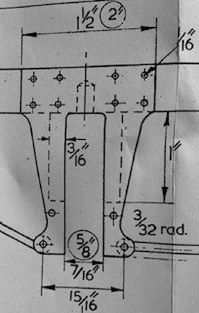
The drawing opposite is for the 3 1/2" model.
Conversion took some time but the length of the 1" piece on the drawing for 5" model is 1 1/2" still with thickness of 3/16" but depth of 3/8".
That leaves 4 more to do for the leading axle box then more metal bought for the centre axle horns and then they will need soldering and lastly the training axle horns but the length of the pieces needs to be calculated.

The top on is cooling the lower one is cool!!
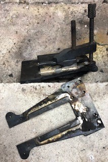
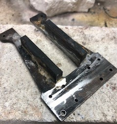
Supply of steel arrived so I was able to cut four more pieces and silver solder to the mid axle horns.
Also collected from MMES were the issues of Model engineer showing the variations of the parts for the posts value movement.
This is the information :-
LBSC's drawings produce a locomotive with the outwards appearance of Lion, not a scale model. There is a letter authored by Charles E Taylor-Nobbs on the subject with suggested corrections to produce a more accurate representation in Model Engineer magazine Volume 150, issue 3705, 20 May 1983, page 620.
The gab valve-gear as drawn by LBSC cannot be reversed except at certain crank-axle positions. Modifications with dimensioned drawings applicable to 5" gauge Lion locomotives were authored by L A Saxby in Model Engineer Magazine, volume 139, issue 3479, 21 December 1973, page 1222. He also advocates modifications to lock the screwed valve-rod glands and addition of a bridge piece to the end of the rocker-arms to cope with excessive strain.
Further comments on the gab valve-gear including an improved valve-rod gland and other suggested improvements are covered in an article in Model Engineer magazine by K C Miller in Volume 150, issue 3707, 17th June 1983, page 714.
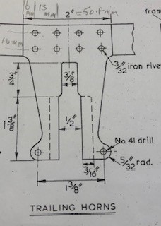
The plans showed the 5" gauge trailing axle and the 1 3/8" parts needed.
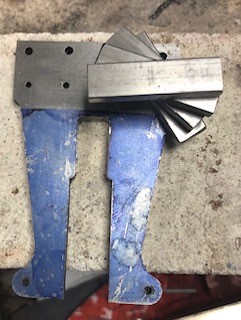
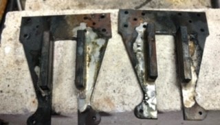
Leading horn soldered
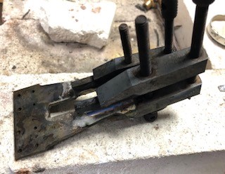

Surplus Silver solder filed away so that the part sits well on the frame steel.
