
Making out another boiler plate. This took much longer than expected as I had to keep checking the measurements but is ready to have a hole cut ready to flange to go over the boiler barrel.
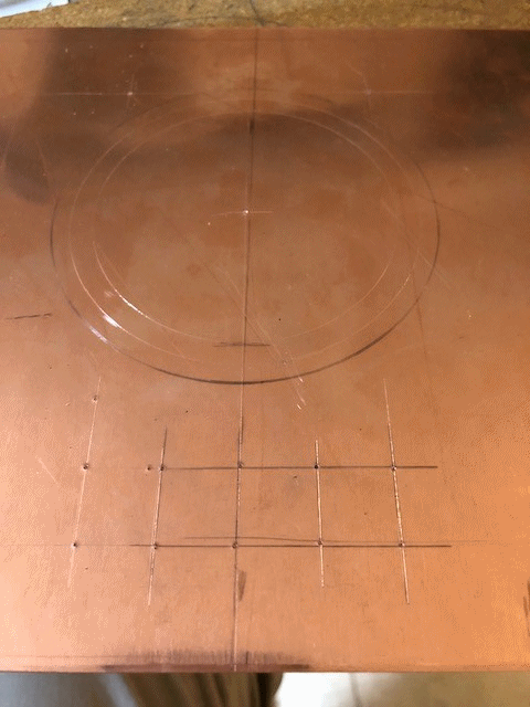
Using my new Jig saw the necessary hole was cut in the copper sheet
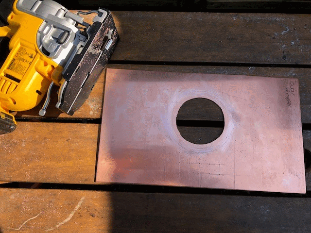
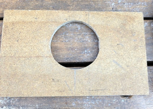
I still have to mark out the supporting said.
I have also order a new Sievert handle and burner nozzle as mine were bought in 1981 so are perhaps past there best !!!
Whilst waiting for a new burner for the propane bottle to arrive I have decided to turn my attention to machining the driving wheels.
On the drawing the dimensions are given in inches and fraction of an inch but I work in mm. So I have had to do a conversion including reference to Page 3 of the July 1953 issue of Model Engineer.
The overall diameter of the tread is 134.93mm
The hub is raised 3.17mm
The depth of tread is 3.96mm
The width of the tread is 14.28mm
The width of the flange is 2.38,,
The hole for the axle is 11.11 mm (7/16" reamed)
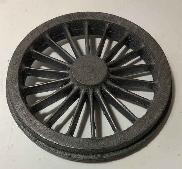
Clean up the flange of any casting surplus
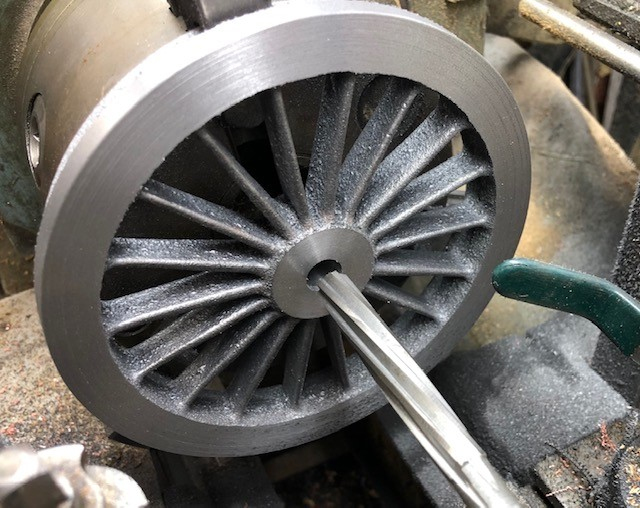
Chuck the wheel casting by its tread, then face the back bore for axle and ream, lastly rough turn the flange.
The reverse the wheel and hold by flange and turn the face and boss.
After about 2 hours gentle turning the photo shows the result with just 0.7mm remaining to be taken off the back face.
The flange was cleaned up on the linisher and then the wheel put into the Three Jaw chuck and run to check for approximate true without wobble.
So far so good.
Using the revolving centre the outer part of the flange was turned down to just over size.
Then the back was faced, first the protrusion of the boss was removed and then a centre drill used to remove the small pip and allow the revolving centre to be use whilst the outer part of the back face was machined and then removed on each pass to keep parity for the centre part.
Calculation made that revealed that 1.71mm need to be removed from the back face and similarly from the front to keep the location of the spokes as caste.
With the final 0.7mm taken off it was time to further centre drill and then drill out ready to bore the axle hole before final reaming.

Now repeat 3 more times for the other driving wheels.
Sadly work was brought to a sudden half as the lathe stopped turning !!
The motor was fine but Due to lack of maintenance on my part by not completing the oiling up of the machine as should be done suddenly whilst in BACK GEAR the lathe stopped rotating.
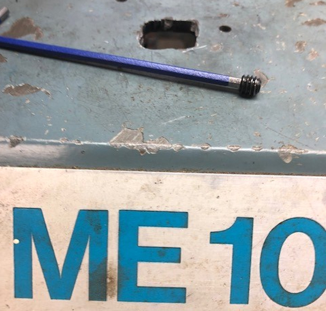
After a lot of thought and viewing of YouTube video, reading and re-reading the Know you lath book, I discovered that in a pulley wheel inside the headstock was a grub allen screw which was there to prevent dirt entering the spindle pulley. The screw needs a 1/8" allen key to remove "grub screw plug" in the "V" of one of the pulley sheaves inside the headstock, squirting oil into this lubricates the pulley when back gear is engaged. to say the least this is a very fiddly job but as I found out essential essential for longevity of the lathe to work in Back Gear.
The removal of the allen grub screw.
The picture shows the hole I made in the top of my casing as it was just too difficult to access the grub screw from the rear !!
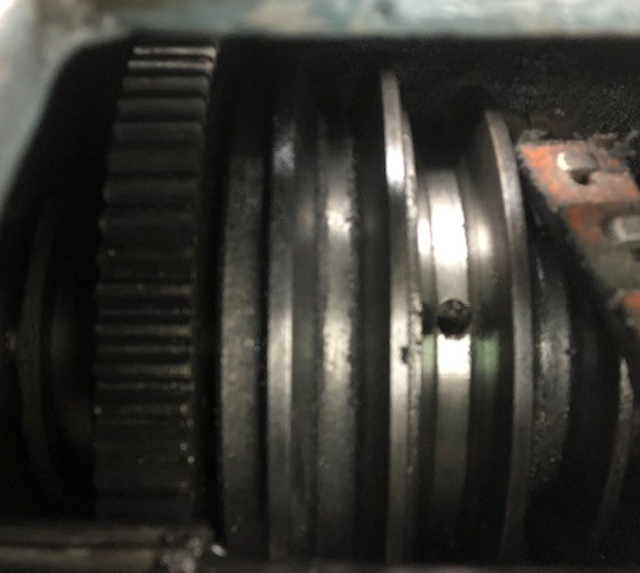
The oiling was completed and the lathe was turned by hand ..More oil will be applied before running of power !! I plan to cap the oiling hole with heavy grease !!
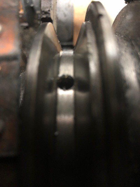
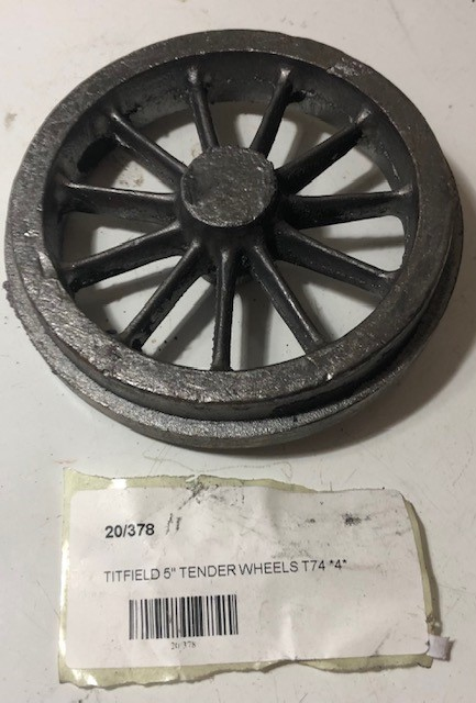
The second one followed but enough for today !!
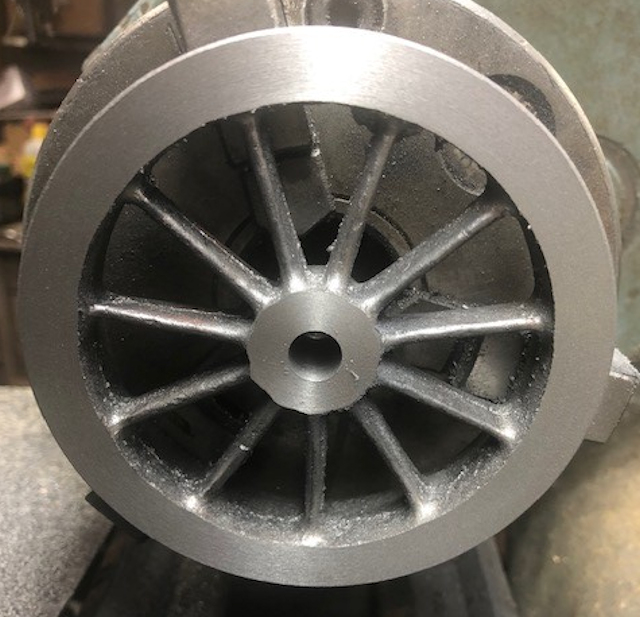
Re-oiled up the Lathe and completed the machining of the back of all four tender wheels

The front side to the Tender Wheel were maching to size including the raised hub. I used a spacer the correct thickness between the front and the tool to gauge the correct amount to remove.

The driving wheels ( three of them ) were finished to size leaving as with the tender wheels the tread to machined.
The wheels being so large I had to hold them in a 4 jaw chuck.
The blue distance piece to being used to gauge the 1/8" that the hub entends beyond the front face of the wheel.
