
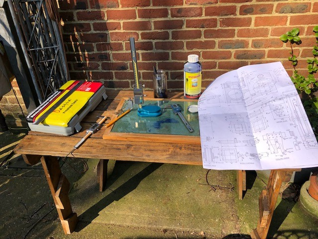
Measuring using my new measuring gauge and very easy to use to !!
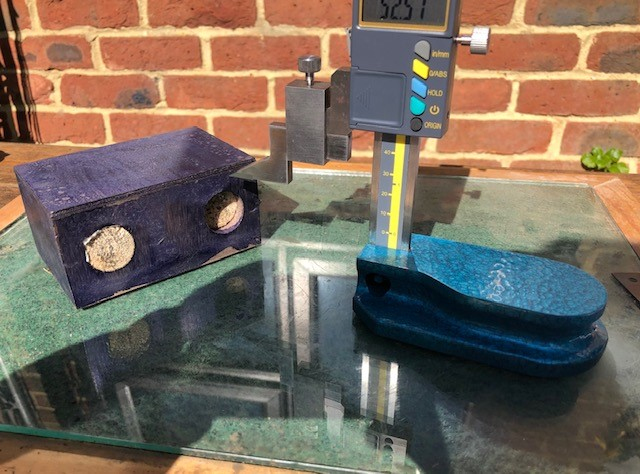
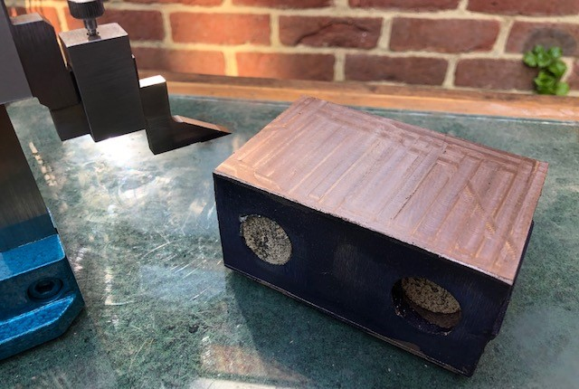
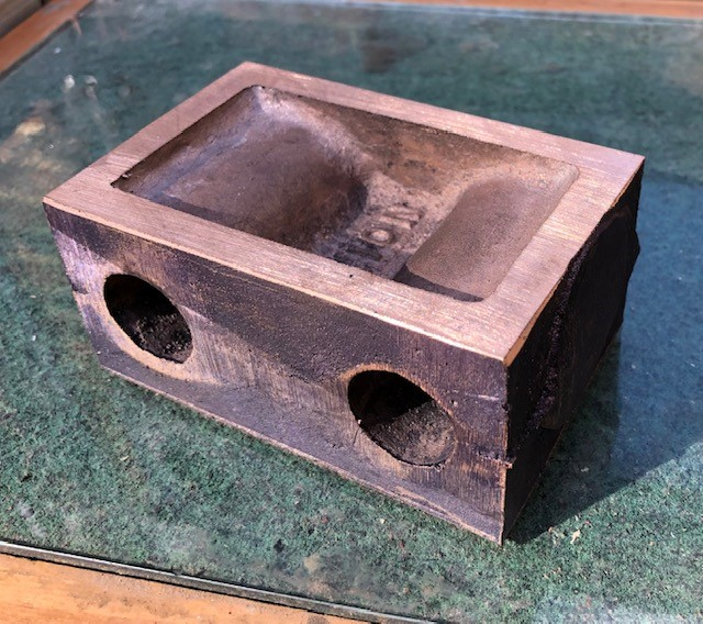

It was only a little off so a tap or two with the soft hammer put the right and the final cut was made.
It was then turned over end for end and the other end machined to a base level.
This is now ready to be marked out for boring !!!

After a chat with several friends it was the marking out prior to boring the cylinders
I used a DTI to check that the block was set parallel to the saddle .

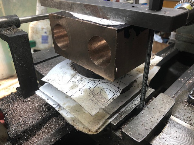
Whilst the setting up shown above was fine I decided to put a piece of paper between each of the metal surfaces to try to ensure no movement.
The gibs were also tightened in the saddle so that no lateral movement would take place until the end of the boring of the cylinder.
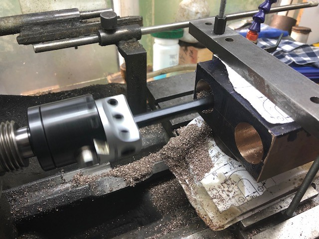
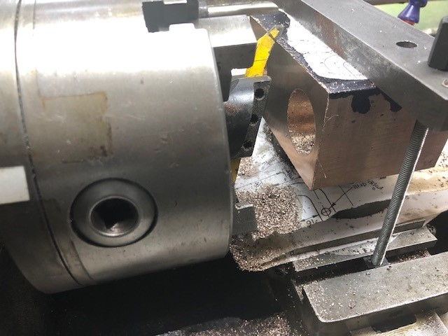
This photo show the first bore with the new boring bare.

So the cylinder block was coated in marking out blue and the position of the ports marked out and cross hatched so that there should be no mistakes.

The vice had previously been set square to the travel by using a dro so now we can porceed with the set up ready for cutting.
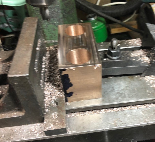
This is my setup for machining the various ports. Note the two machine clamps which are acting as stops at the end of each cut.

A stop on the depth was adjusted and also the DRO set to zero. The cuts were made very gentle as the cutter was only 5/23" slot drill.
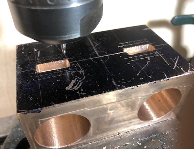
Machined the steam inlet ports They may not be perfect but are very close !!!
To help me in the future I have bought a DRO from RDG Tools !!!
