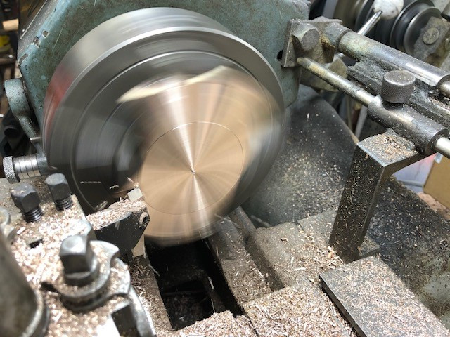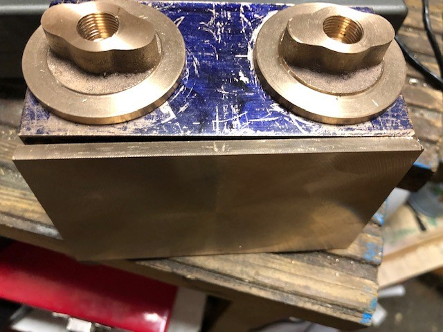
Today I will make a start on machining the end caps. These must be made to a good register to the cylinders particularly the end where the piston rod exits as the hole and the fit must be concentric to the bore.
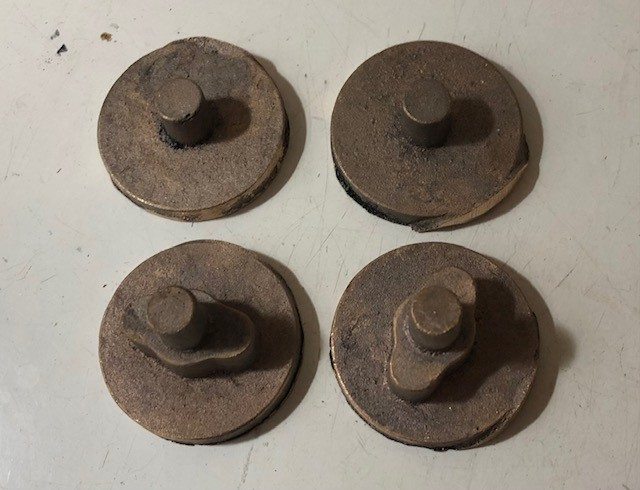
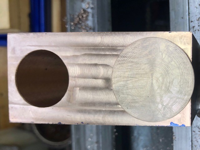
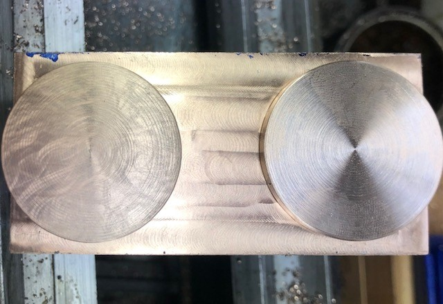
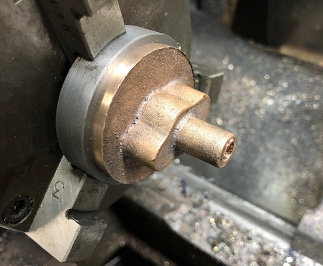
With a day off yesterday as doing loading duty at the MMES club I decided to complete the first end cap with the hole for the piston rod.
First the extension was measured ad depth stop located and then the top was machined away and the holding spigot also.
The the end was drilled to take the 7/15" x 26 tap.
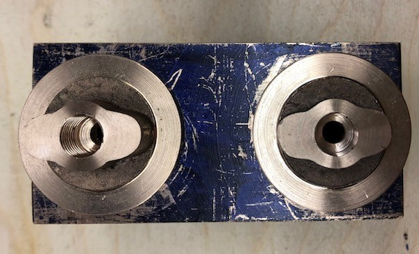
Now all completed except for drilling the the two holes to be tapped to take the cross head supports..
This cover goes on cylinder 1 and was so marked.

Fitting my new DRO (Digital Rad Out) to my mill
Photo shows the display
I may re-position the display when I find out if it is difficult to use in the current position.

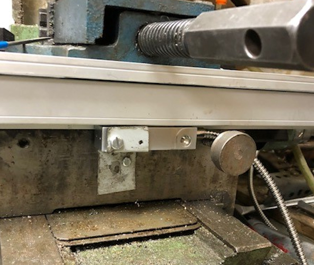
Fitting the Y axis.
Drilling for the two bolts to hold the backing strip in place took for ever and my left arm know I had purt it through a workout for 2 days!
Making up the fitting to hold the fixed part in place was much easier and only one hole to drill and tap for M5 bolt.
Now I need to figure out before ordering the necessary part how to fit the z axis scale !!

These days were taken up ordering and then fitting the Z axis.
The photo shows the start of the fitting with a piece of Aluminium being fitted to the front of the Mill to act as the holder for the fixed part.
A spacer was used so the the bar extended out beyond the cover of the pulleys. I have yet to drill the check alignment at the top.
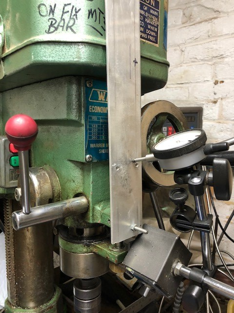
The mark on the unit shows where I wish it to be when fully retracted.

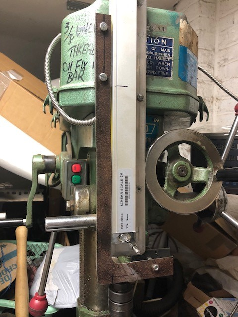
The Z axis actuator was connected to the movable part of the mill by cutting out an "L" shaped piece of steel and the drilling and bolting into position.
The packing piece was unbolted and then the movement checked,
Upon lowering the quill and returning it to dial read the same so pleased it is all OK !!
So now ready to continue wit the loco build !!
The first cuts across the steam chest top showed how out of square the casting was. Still there was plenty of spare metal that could be cut away.
Note the cutting tool for the first cuts !!

The result is quite pleasing.
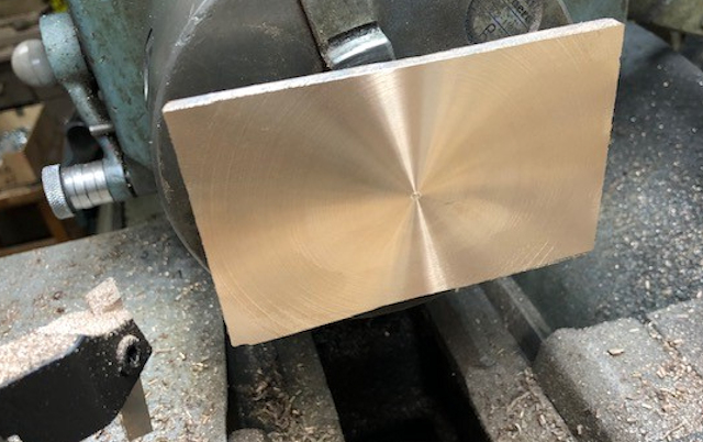

A light cut was made and a check made for Right Angle to the long side. The Vice was fractionally adjusted twice more after light cuts until it was set at right angle to the long side. The width was then brought to size to fit the cylinder.
This took about a couple of hours of careful work and the DRO performed very well.

