The Diary of the Building of a 5" gauge Stirling Single
|
|
|
|
|
|
|
Bogie horn blocks, axle boxes and axles |
|
| 26th Jan 2008
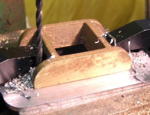
Drilling one of the rivet hole for the bogie horn blocks |
 |
| The bogie frame with horn block now riveted in place. | 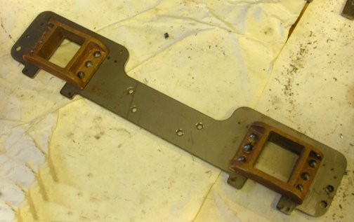 |
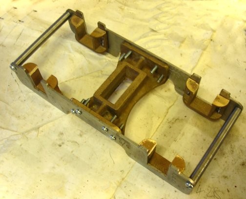
| The bogie with all four horn blocks
in place.
NOTE the screws used in the picture are for initial construction only. Counter sunk screws will be used in the finished item. |
 |
| Machining out the centre of the bogie stretcher. | 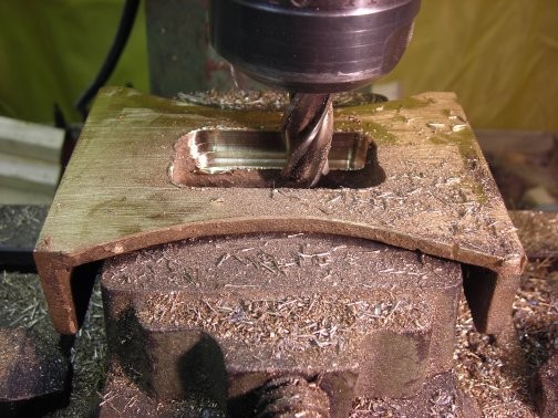 |
| The centre finished along side the un-machined centre piece. | 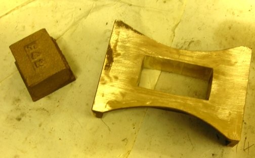 |
| The centre piece has now been machined. Working out how to hold the piece down and still have enough room for the milling cutter to pass took a long time to workout. Eventually the piece was first turned rectangular in the lathe and then drill and reamed and then that hole was used to bolt it down as shown. | 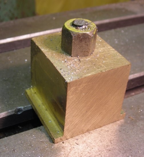 |
| The centre bogie stretched tried on the centre piece to check for size. | 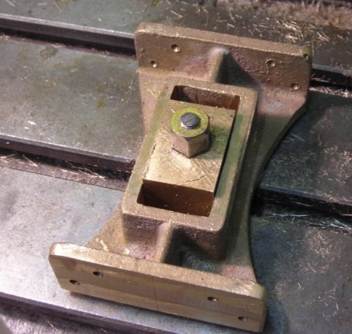 |
| All parts re-assembled to the bogie. |  |
| 27th Jan 2008
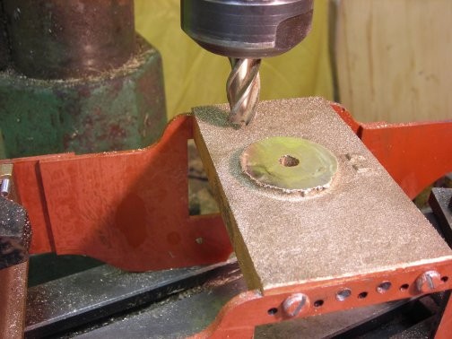
The bogie stretcher on the main chassis was now machined and hole drilled and reamed to size. When assembly was made it was discovered that :- Whilst all parts had been machined correctly the bogie stretched was 3/16" out of position all due to misunderstanding the plan. This will result in the needing to be re-drill and tapped to bring to correct position. |
 |
| 28th Jan 2008
The making good the error mentioned yesterday was achieved by filling the tapped holes with threaded brass rod fixed into place by LOCTITE 601 engineering adhesive. |
|
| 29th Jan 2008
Today the machining of the horn block took place. The picture shows the basic set up with protective plastic screen to prevent the fine shaves of material from having a chance to hit me in the face. The plastic is quickly removed and replaced by taking out the chamfered piece of wood on the right hand side. |
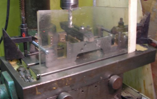 |
| Even with the best laid plans things
can go wrong.
Even thought I had well clamped down the frames the milling cutter on two occasions came lose in the mill and everything had to be reset - but with little damage but on the third time it came loose it did make rather a mess of a side but thankfully nothing put out of square too much that a little hammering did not put right. The picture shows the completed bogie machined. Lesson learned Tighten the boss holding the mill attachment just a bit more than is thought necessary !!!! |
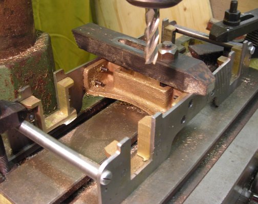 |
| 30th Jan 2008
The casting for the axle boxes for the bogie were set up VERY firmly on the bed of the milling machine - learning from the mistakes earlier!!! Both sides were machined to size. One edge was marked so that it could be identified after the casting was cut up to enable the axle boxes to sit in the horn blocks in the same orientation. All will become plain in the following pictures..
|
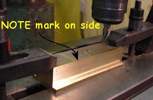 |
| Of course the band saw does not cut straight enough so each axle box had to be machined up in the lathe so that top and bottom were parallel. The picture show the set up. | 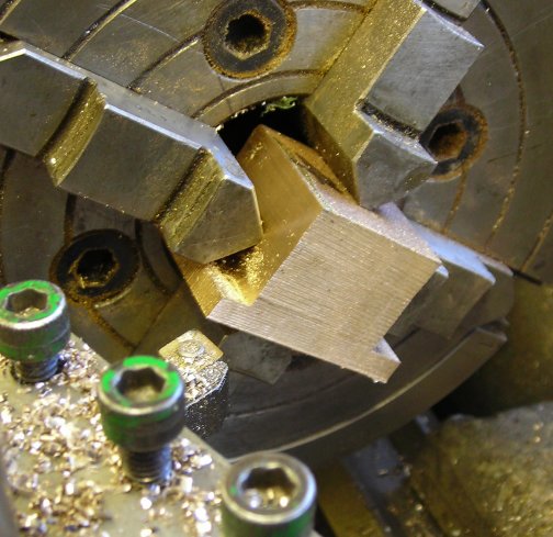 |
| The four blocks were then numbered and you can still see the side mark. | 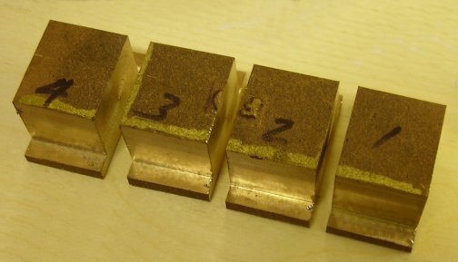 |
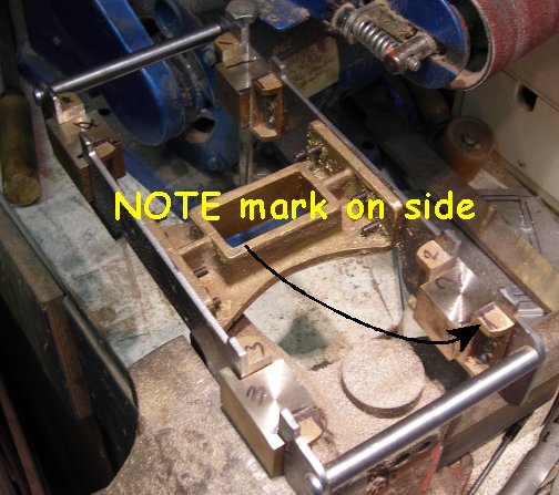
| The axle blocks were then fitted
by filing to the horn blocks.
The horn blocks were also marked with the block number and the side mark. All side marked face one way thus making the blocks similar for drilling.
|
 |
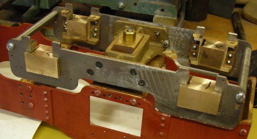
| The bogie now has the axle box in
position.
Please excuse the diagonal marked just behind the axle box "1" but that is where the error in machining took place and I was lucky not to break the milling cutter. |
 |
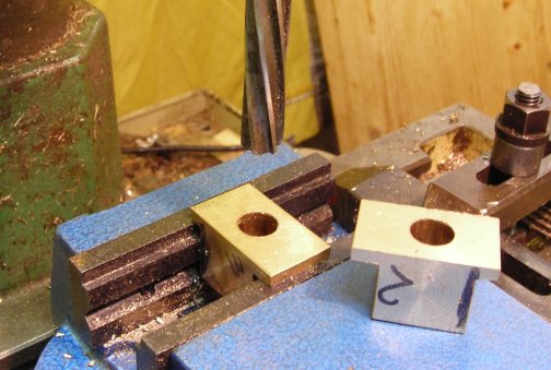
| The picture shows the set up for
drilling and reaming the axle boxes.
The "new" machine vice was set square to the travel of the mill and then the centre where the hole was to be drilled marked. As the centre line from the similar side was the same with the machine vice locked in position front to back all that had to be aligned was the side to side which was done with the laser pointer. However the first pair were marked out bottom for top but all is well as I was able to turn the part over and it fitted just as nicely. The second set seen in the picture took but a fraction of the time to do the first pair and proved that the method is viable. |
 |
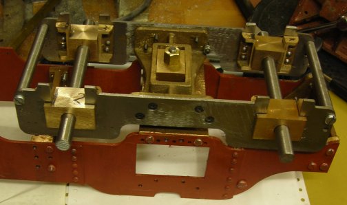
| The 1/2" axles passed through the
axle boxes and any tightness was easy off with slight adjustment to the horn
blocks and axles box sides. there needs to be some slop but not too much
else the axles would bind in the blocks as the loco goes over the track.
The axle boxes still have some finishing off to do such as oil ways etc. |
 |
| 31st Jan 2008
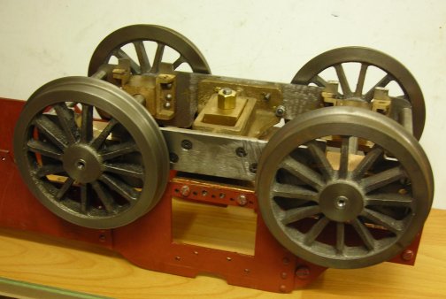
The axles were machined to size and the wheels placed in position. They will be fixed with Loctite engineering adhesive in due course after all remaining parts on the bogie have been completed. |
 |
