The Diary of the Building of a 5" gauge Stirling Single |
|
|
|
|
|
|
|
Completion of the build Part 22 |
|
| 16th
Jan 2020 continued from previous page These are the 5BA bolts which holed the regulator in place. DO NOT confuse these bolts with 6BA which are only a little smaller. |
 |
17th
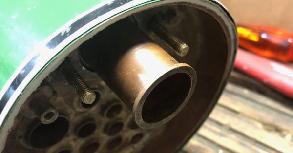
Jan 2020The re-building of the Regulator.A rather special day so loads of photos taken to help me recalled if necessary how I achieved the installation.The steam collecting tube goes in and a check is made to ensure that the holes in the top of the tube are uppermost |
 |
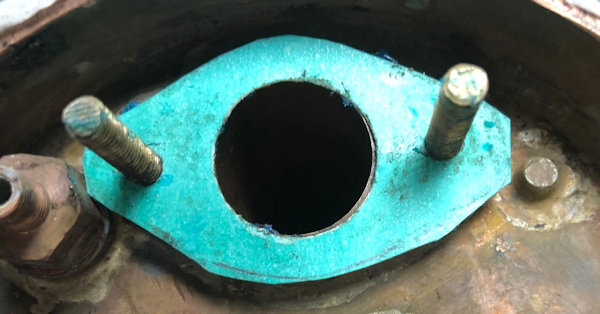
| Assembling
the regulator started with cutting out the gasket to go between
the fitting linking the steam pipe to the super heaters. The gasket sealent was applied and the gasket pushed over the stub bolts. |
 |
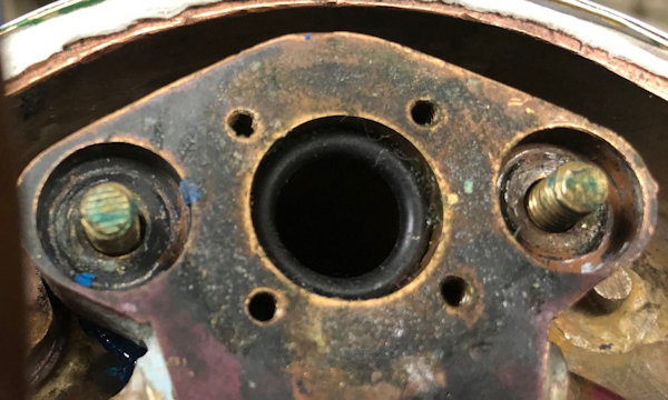
| Then
Header with the super heaters was put into place with a little
help from a soft hammer. Note that at the moment an "O" ring is still in place so that I did not loose it !! |
 |
| The
header was bolted down using a torque wrench and then the
regulator actuator pushed into place. |
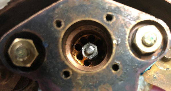 |
| The Gasket for the operating end was cut the application of sealant applied to the actuating part and then the gasket placed in position paragraph the actuator was then slid into the retaining barrel. |  |
| The
photo shows first stage of bolting down with 5BA bolts was
carried out so that the gasket sealant can cure a bit. It will
be further tightened down to complete the assembly in due course
and also a check made at the front end. |
 |
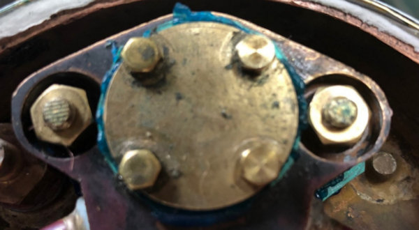
| The
"O" ring was positioned as an aid to sealing the regulator
closing and then tthe is the front end was closed up using another gaskets and gasket sealant. The 6BA bolts was torque wrenched down.. |
 |
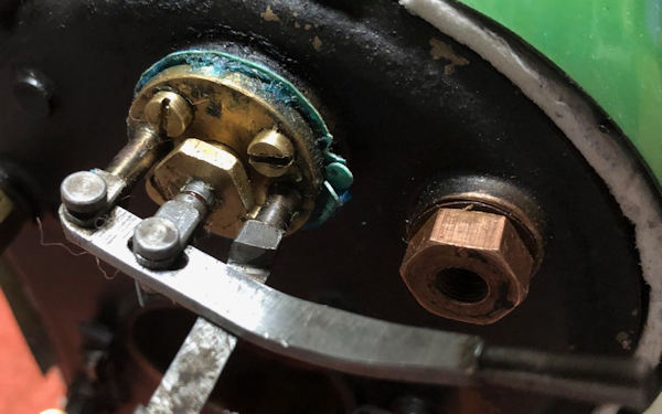
| The
rear end now completed including the brass nut holding in place
another little "O" ring and the operation checked all ok ! |
 |
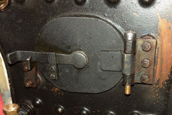
| 18th
Jan 2020 Notm uch time to day so an installation of the fire door which also made me see the need for some more high temperature paint to the right. |
 |
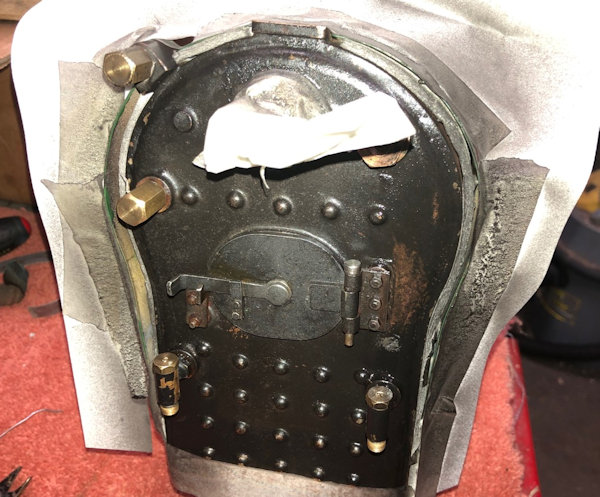
| The
area where over spray might occur was covered up and the light
coat of paint applyied. A further caot will be applied when
fully dry. |
 |
| Another
coat of the black high temperature paint was sprayed on. then the turret was fitted. This has 4 6BA studs which are positioned in the threaded hole first, then the turret has the gasket compound applied and it the positioned over the stud and push down so that the spigot engages. Them the difficult part comes of putting the 6BA nuts on the studs. Good light and the uses of long nosed pliers were used and eventually with all nuts in place they can be tightened down evenly with a narrow 6BA spanner. |
 |
| 19th Jan 2020 Whilst at the London Model Engineering Exhibition I chatted to fellow engineers as to the problem I had had fitting the 6BA nuts to the studs for the Turret. The idea is to apply a piece of masking tape to the side of the spanner and then trim round as necessary and finally place the nut in this case a 6BA nut which will be held in place on the masking tape to enable one to engage the first thread. There after the spanner can be used normally with masking tape removed. |
 |
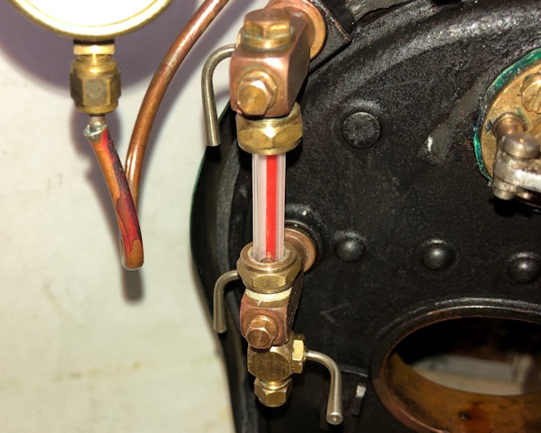
| 20th Jan 2020 The sight glass is reinstalled. I have used red line glass tube as it shows up the level of water very well. I also made a other bung for the blow down outlet as the previous one weeped a little on the hydraulic test. The boiler is now ready for a trial pressure test to check out the fittings. |
 |
| 21st
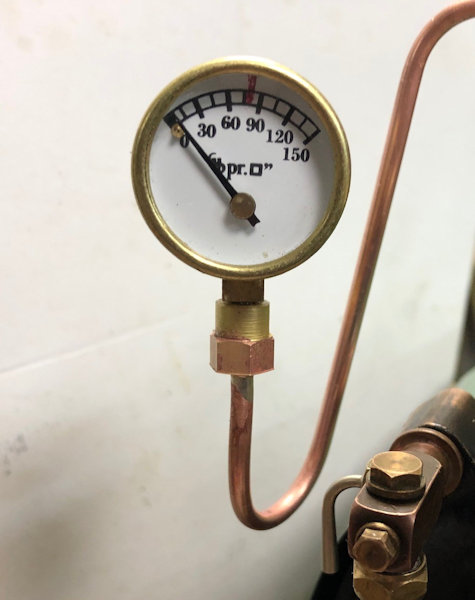
Jan 2020 An idea to improve the look of the link to the pressure gauge was given to me so a new fitting and pipework was made up. I do agree it looks much better. Now need to test it all !! |
 |
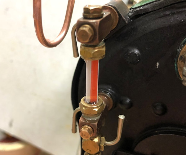
| With the boiler full
of water as a pre club pressure test the red lined glass clearly
shows the water fully in the glass. Ok there is a slight weep
but that can be a slight tightening up at the club for the real
test. The rest of the re-build can continue. |
 |
Next Page |
|
