The Diary of the Building of a 5" gauge Stirling Single |
|
|
|
|
|
|
|
Completion of the build Part 23 |
|
| 21st
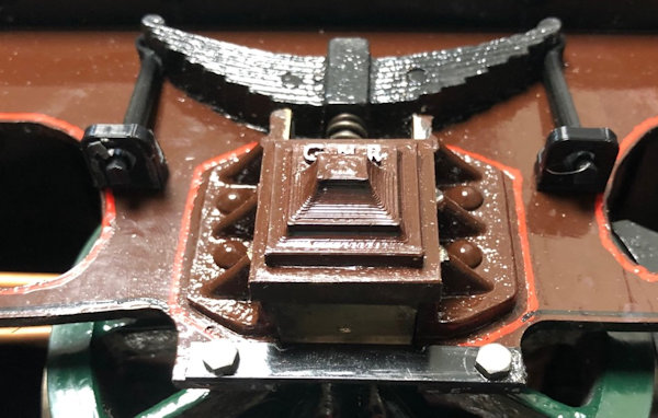
Jan continued from previous page Dummy spring holders 3D printed and adhered with Super Glue by ROCKET I can only do one side at a time to allow the glue to cure. |
 |
| Applying
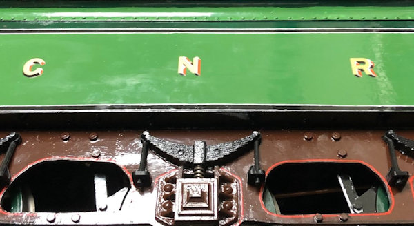
the transfer graphics is something I had not done for about 55
or more years when I used to make Airfix plane kits. I recalled
that then the transfers when put in hot water curled and then
opened and then were ready to use. Not so with these as I had to rescue the first one as it had floated off the backing which the instruction say do not allow as I had left it in far too long about 20 seconds. With the next two I just put one in the hot water at a time for about 2 seconds and it then readily floated off and was easy to position. About 2 hours later the second side of the tender had transfers applied. When they have fully dried, recommended after 72 hours, a coating of clear varnish will be applied before doing the other side.. |
 |
| 22nd
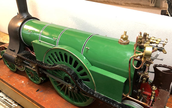
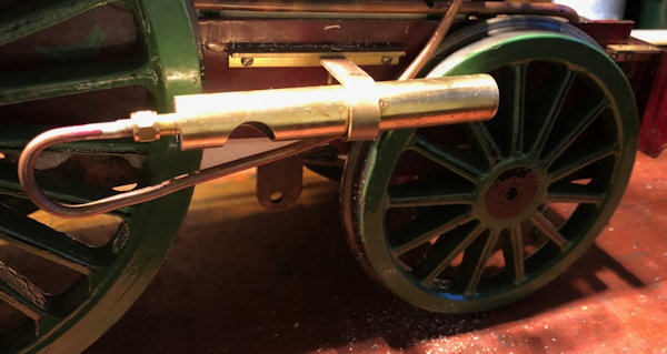
Jan 2020 The boiler is back on the chassis and coupling up of the pipework started. A notch was cut out of the cab to allow for the dummy whistle pipe access to the dummy whistle. |
 |
| 23rd
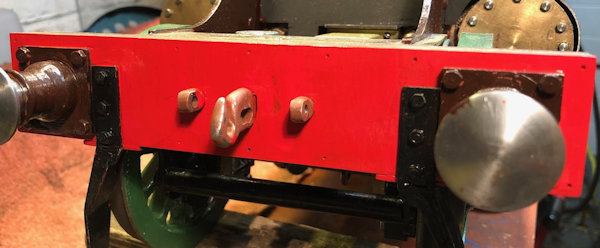
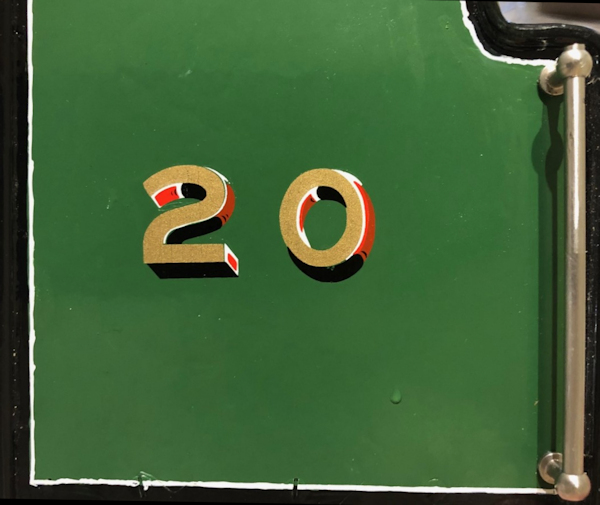
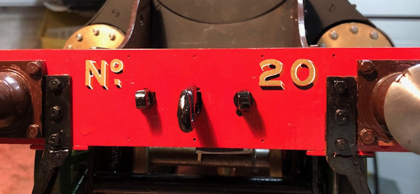
Jan 2020 Before I can apply the transfers to the buffer beam I decided to give it several coats of paint. The first one has been applied and the next tomorrow. The black of the hook and chain holders were painted when the Red was dry to touch. black. Black on the cab was also touched up where it had suffered some knocks since previous painting. The transfers for the buffer beam and the side of the cab arrived this morning from Precision Paints. I now need to decide what number to call the loco. It was started in 1990 and is to be completed in 2020 so a number referring to those year would be good. The numbering of the actual Stirling Singles were not consecutive so I have decided that as the model is to be completed in 2020 that it will be numbered 20. |
 |
| 24th
Jan 2020 Transfer put on each of the cab sides. See above for the reason for the No. 20 chosen. |
 |
| This
set were even more difficult as the letter "N" was separate from
the "o" and the "." but I achieved it in the end ..Again only 2
seconds required in warm not hot water !!! |
 |
| 25th
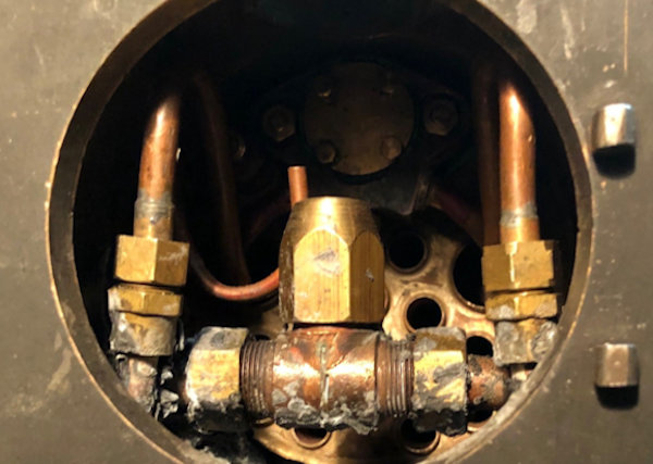
Jan 2020 I was able to tighten down all the remaining union nuts. The two most difficult were the two shown in the smoke box. The smoke box door was fitted, closed and an air supply coupled up set to a maximum of 80 psi. With the Reverser set to forward and the Regulator cracked open the wheel went round and round. A little easing of the cladding at the top of the wheel was necessary as with the thicker insulation the wheel bound slightly. With that adjustment made the wheel went happily round and round and the regulator shut and opened well. I not from the photo that the blower outlet need slight position adjustment. |
 |
| 26th
Jan 2020 A morning visit to my club in Maidstone to discuss the plans and how to make the cab floor resulted in several ideas for me to consider. At home I decided to varnish over the transfers which was easily achieved. Also a small blemish on the paint of the boiler barrel cladding was given attention. The whistle was repositioned so that the side pieces could be removed without having to detach the whistle as well ! |
 |
| 27th
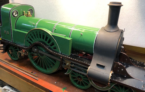
Jan 2020 The side piece all back on and now just the cab to fit. With the 1mm thicker Insulation there needs to be a spacer fitted to the bottom of the cab so let it meet the side pieces. The thickness of the metal was selected and cut to length and then drilled and given a coat of black paint. It will dry / set over night. |
 |
| 28th
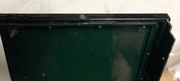
Jan 2020 Not easy to see but I had to provide spacer at the bottom of the cab sides to take account of the 1mm thicker insulation which brought the cab sides a little higher than originally when thinner insulation had been used. The steel pieces are held in place with a 8BA countersunk bolt and I also used Super Glue to hold the piece in place during final fixing of the cab. |
 |
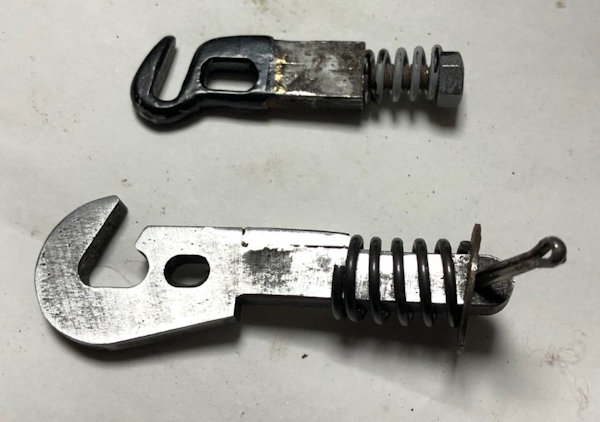
| The
photos shows the original tender hook but as I use the one below
on my trolleys which are designed so the a coupling bar cannot
come out but the shaft was 3mm thinner in height so a piece of
steel was silver soldered into place and the all filed to fit.
The modified hook is not painted ready to be finally fitted. |
 |
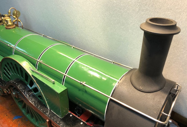
| The
hand rail is tried for the first time since the blind bushes
were fitted and I am delighted with the result as all the
fitting are in line and at the same angle. Many thanks to those
at Maidstone Model Engineering Society who helped me achieve
this by practical guidance and actual physical help in the
silver soldering.. |
 |
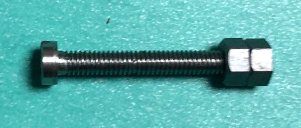
| 29th Jan 2020 The rear buffer of the tender painted red and when dry the hook can be installed. That was the easy part. Then in the afternoon more time on the loco fitting the cab and fitting the hand rail end nuts. Very difficult and in the end when I could not get a small socket to make the nut bite I then though well nut lock the nut to go on the end of the hand rail by jut a thread and then wind it on, with it in place use a pair of long nosed pliers and a screwdriver in the cross head of the bolt to loosed the lock nut. The idea worked and then I had the nut on the hand rail end which I could then tighten with the socket. |
 |
| So here is the Stirling Single as it appears at 17:30 today with the only thing remaining is the making of a floor for the cab and making a gap (fall) plate to link between the loco and the Tender. | 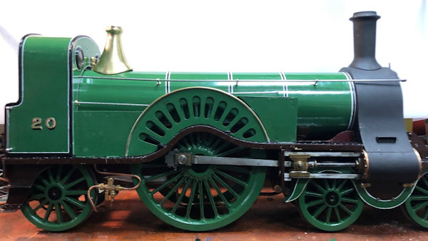 |
| 30th
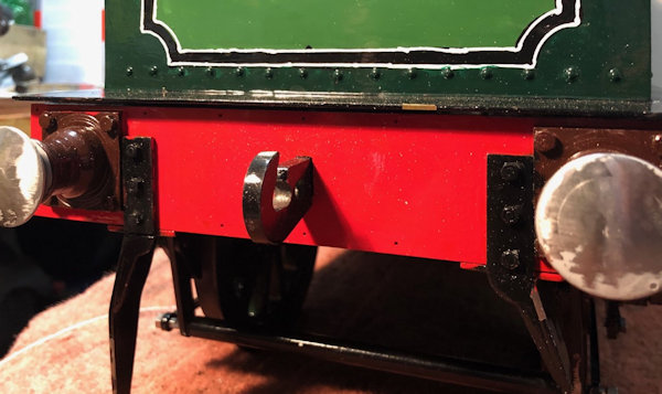
Jan 2020 The tender coupling hook fitted not very easy as I had to compress the spring and also insert the locking pin but done now !! Sadly the close up photo shows that I have a lot to learn about lining out !! |
 |
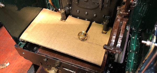
| 31st Jan 2020 Template for the floor of the Cab. |
 |
Next Page |
|
